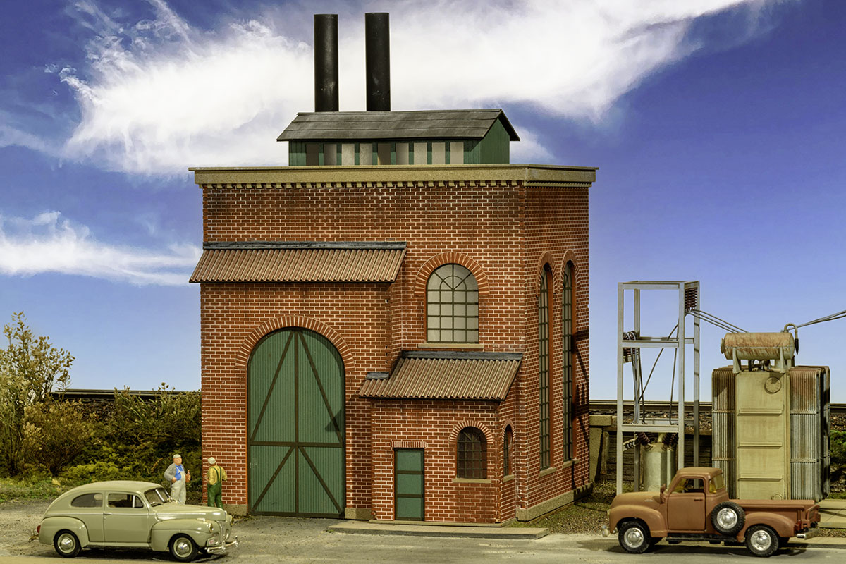
Introducing the first kit in my Dennis Brennan Signature Series. The Garfield Electric Substation—a brand-new, original O-scale laser-cut kit that brings historically correct realism to your layout. Other Garfield City structures are being developed. Whether tucked into a cityscape or powering up a remote rural scene, the Garfield Electric Substation is the perfect addition to elevating the realism and operational storytelling of your railroad.
A Brief History. At the dawn of the 20th Century, power plants were smaller and scattered across cities, often supplying electricity to a specific neighborhood or district. These plants were typically powered by steam engines or water turbines.
As large, centralized power plants were developed to meet the increasing electricity demand, local power stations were often converted into substations. This involved retrofitting the existing structure by removing the generators, and adding transformers, switchgear, control systems and other necessary equipment for substation operation. If the substation’s electrical capacity needs ever exceeded the space available, outdoor substations would be established next to the indoor substations, space permitting.
Also, in the late 19th and early twentieth centuries, there was a significant shift towards electrifying railroads and trolleys. Railroads often utilized a primary substation that received power directly from a power plant and smaller interconnected substations, allowing power transfer between different sections of the railway system. Streetcar lines also placed substations along their routes to ensure even power distribution.
The above bit of info is important, since providing a history (real or imagined) for any structure will help you understand the when, the why, and the wherefore of its being. Armed with that information, you can realistically locate it in a time and place. This then helps you provide the necessary details that will breathe life into your modeled reality.
For instance, assuming it was originally built as a powerhouse, it would have needed fuel to operate the turbines. So, it would have either had a spur to drop off coal or been located by a waterway. Depending upon the era you’re modeling, it could be a small local power plant, an electric substation, or perhaps converted into some type of factory. I chose to present it as a small, previously coal-fired power plant that was converted into a substation, but the choice is yours!
This easy to build laser cut kit features interlocking walls, basswood doors, and peel and stick windows. The mounting board main roof is covered with included gravel, while 3M sticky back tarpaper strips cover the cupola roof. The office and garage roofs use 3M sticky back corrugation over mounting board. The complete photographically illustrated instructions are a primer on kit construction geared to the beginner.
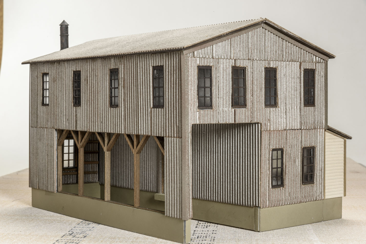
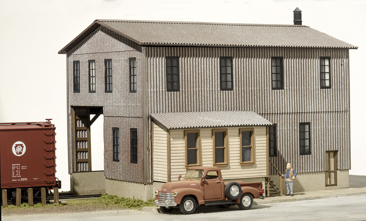
Introducing the 4th kit in my highly popular Frank Ellison Tribute Series: The Sanky Wanky Coffee Co. Recreating these iconic structures have given me an even greater appreciation for what he had accomplished. Ellison’s buildings are perfectly proportioned. Many of his structures were based upon actual buildings that he selectively compressed. And that, my fellow modelers, is an art.
Now, while I have added my personal touches to these buildings, I have not altered his dimensions. Some buildings still exist and I have photos of them. In many cases, Ellison would only finish three sides of a structure, if that’s all one could see. However, sometimes he did pencil in the positions of a one or two windows and a door. In those cases, I have followed his lead. Otherwise, I fill in the blanks. Regardless, anyone who knows his work will recognize my rendition as an Ellison recreation.
The Richmond Packing Co. is the 3rd kit in in my Frank Ellison Tribute Series. The footprint is10-1/8 x 12-1/2 which includes the freight dock.
Frank Ellison was a pioneer model railroader back in the 1930s, 40s & 50s. He was considered a top name in the field and his beautifully built Delta Lines was perhaps the most widely known model railroad in the world according to John Page, the editor of Model Railroader Magazine in the early 1950s.
Frank authored a series of articles on all aspects of model railroading. Of particular note were his “How-to” pieces on scratch building the structures he created for his railroad. Back then, there were no building kits and detail parts like we have today. He made most everything out of cardboard with the features like planks or bricks drawn in with ink and colored with oil base artist colors. So, I am bringing these structures back to life with my spin on them. The idea is that if Frank were alive today, this is how he would do it—using modern methods and materials. I’ve included a reproduction of his article that appeared in the November 1946 issue of Model Builder magazine – a Lionel publication
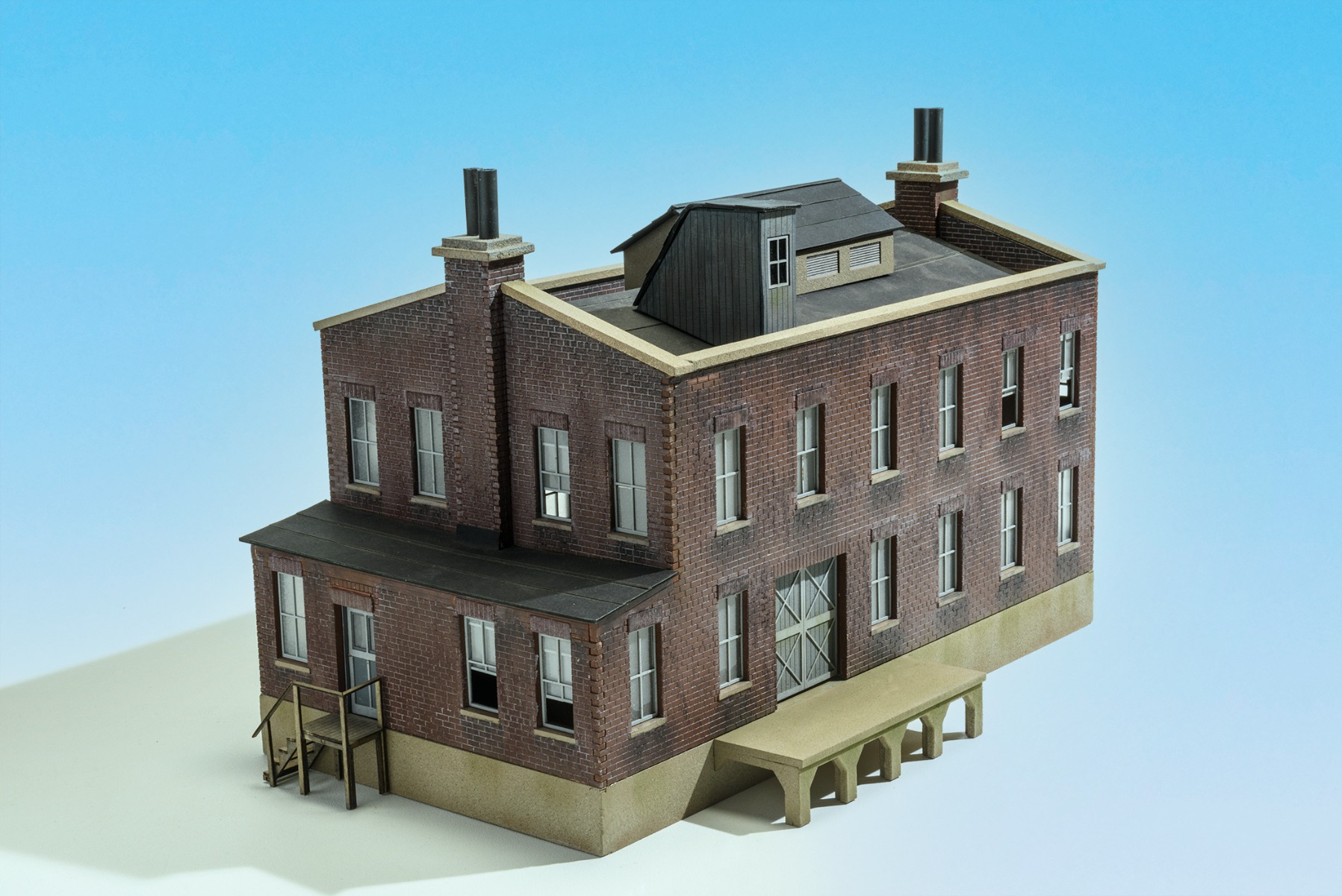
In his 1946 article, Ellison described this building as an “old brownstone residence built perhaps 75 years ago for the richest man in town and subsequently abandoned.” (This would date the structure to 1871). “We shall suppose that some of the partitions were ripped out, a window or two bricked up, other windows enlarged into doors, a heating plant, boilers, and vats installed, and a condenser put in for the cold room. Short fat pipes and a ventilator pierce the old slate roof and a cattle pen occupies the back yard.” He also mentioned “limestone sills” and “blocks of red sandstone… set in brown mortar.” This, then, is part of Ellison’s genius. Thinking about the history of what he was modeling, created a realistic building that showed credible and logical changes over time which accounted for its present state.
Although Ellison saw this as a local meat processing plant, it lends itself to any type of small manufacturing plant. However, for those who would like a place to drop off their cattle cars, a cattle pen will be available separately in the near future.
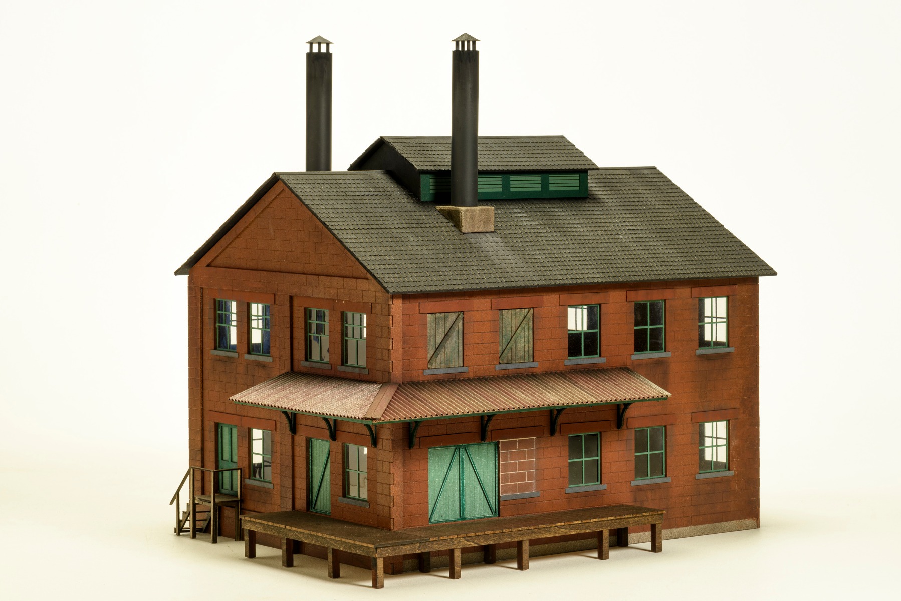
This is the 2nd structure in my Frank Ellison Tribute Series. The kits are available. If you would like to have one of these limited edition kits, please contact me. The overall footprint is 10 x 17 including the shed and the loading platform. (The building’s walls measure 6 x 17. The dock is 1.5″ deep and the shed is 2.5″ deep)
Completely detailed and photographically illustrated instructions show even a beginner how to build, weather and paint this kit. $149.95
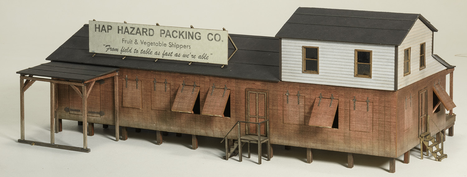
The Hap Hazard Packing Co. represents a farmer’s cooperative. Ellison’s description in the Toy Trains 1952 article sheds light on this local to market industry: “Trucks from neighboring farms line up on the street side of hundreds of roughly planked and unpainted packing sheds,delivering freshly picked lettuce and tomatoes from the fields for tomorrow’s salads a hundred or a thousand miles away–and early peas, asparagus,berries,beets and cabbage. A spur track runs along a loading platform on the other side of each of the sheds and a pick-up train stops daily to wheel out one or two loaded refrigerator cars and replace them with freshly iced and empty ones.”
I was recognized by Classic Toy Trains magazine in the December 2017 issue as one of the top model railroad photographers over the past 30 years. This is in the December issue!
“Let’s turn the spotlight on a different group of photographers, free-lancers hired for specific assignments… More often our free-lancers came from outside, having built solid reputations in the fields of railroad photography and scale modeling”
“Three stand out for the consistently high quality of their work. Dennis Brennan, Steve Crise, and Paul Dolkos have long added to CTT by providing terrific images. We look forward to many more years of collaboration with them.”
“Among the freelance photographers associated with Classic Toy Trains, only Dave Frary and the late Fred Dole rival Dennis Brennan for the variety of their contributions. All three not only submitted great pictures of layouts and collections but they also wrote articles detailing how to create superb scenes and build structures. In some way or another, each had a model railroad showcased in the magazine.”
This is the prototype for the Ob Long Box Co.–the first kit in my Frank Ellison Tribute Series. Frank was a model railroad pioneer back in the 1930s, 40s & 50s. He was considered a top name in the field and his beautifully built Delta Lines was perhaps the most widely known model railroad in the world according to John Page, the editor of Model Railroader Magazine in the early 1950s.
Frank authored a series of articles on all aspects of model railroading. Of particular note were his How-to pieces on scratch building the structures he created for his railroad. Back then, there were no building kits and detail parts like we have today. He made everything out of cardboard with the features like corrugations drawn in with ink and colored with oil base artist colors.
So, I am bringing these structures back to life with my spin on them. The idea is that if Frank were alive today, this is how he would do it — using modern materials.
This will be a Limited Edition kit of 100 and is sure to be a sellout. The cost is $129.95. There are less than 40 left.
Using my prototype for the Oblong Box Co. kit, I’m going to show you how to integrate a rail side structure into your layout. Placement is important when you have rolling stock clearances to take into account, especially when a spur track actually enters a factory. I use the National Model Railroad Association (NMRA) Standard Clearances as a guide for locating the track relative to a loading platform—in this case our interior loading dock wall:
From track center to edge of loading platform – 1 3/8”
From top of rail to top of loading platform – 1”
Since the width of the track entry opening is 31/4, centering our track at 15/8 provides an extra margin of safety. The loading dock height is 1” above the bottom of the structure as is typical for most kits. If you wish to be prototypical, that means the top of the rail should be at ground level. We can do that by either raising the ground under the structure or physically lowering the track. On my layout, I often use ceiling tiles to cover the substrate. I used the same procedure on this diorama which will eventually be incorporated into my layout. It is often easier to do the immediate scenery and details at your workbench especially if the model is to be located in an area that’s not easily accessible.
By cutting out a section in the ½” thick ceiling tile to accommodate the ½” high Atlas O track, I effectively placed the top of the rail at ground level. Additionally, this will provide enough clearance for a scale boxcar. I mounted the building on a 1/8” scrap piece of Masonite to match the height of the sidewalk. Because of that, I also raised the track. Since, I didn’t have any more Masonite, I used paint stirrers. These were only 3/32” thick but that’s close enough. Actually, I could have left them out and nobody would ever notice.
The retaining walls disguise the fact that the foundation stops at ground level. They also add a nice scenic element and serve as a contrast to the sloping ground. They are leftover scraps from another project and came from HO Decorflex foam retaining walls by Faller. Don’t let the HO tag fool you. These cut stones will fit right into an O scale layout. The cork strips alongside the ties were only being used as a placeholder and were eliminated.
Prior to adding ground cover materials, I painted the ceiling tile with a flat medium brown latex paint. This seals the tile and becomes the base dirt layer. A yardstick sidewalk was added next. Then, I added my Fine Natural Earth to provide a bit of texture to the dirt. Notice that I allowed the brown paint to show. The slope along the track sides was covered with both the Fine and Coarse Earth.
Next, I added Fine Superior Sand to represent that gritty texture one often encounters around industrial buildings. I see this as an employee parking area. The ties act as a guard rail. Woodland Scenics weeds and grasses add more color and texture. This also firmly sets the building into the ground by hiding the base. Finally, the street was paved with Durham’s Water Putty. Adding black liquid tempera paint to the water putty when mixing it, provides a nice medium gray color that is well suited for roads.
The diorama base is a 16” x 23 ½” piece of ¼” plywood supported with 1” x 2” framing. The ½” thick ceiling tile is placed bottom side up and then painted. I had initially made the cut out 3 ¼” to match the building opening. Then, I decided to match the track width instead, so I added the unpainted ceiling tile strips to abut the ties inside the structure.
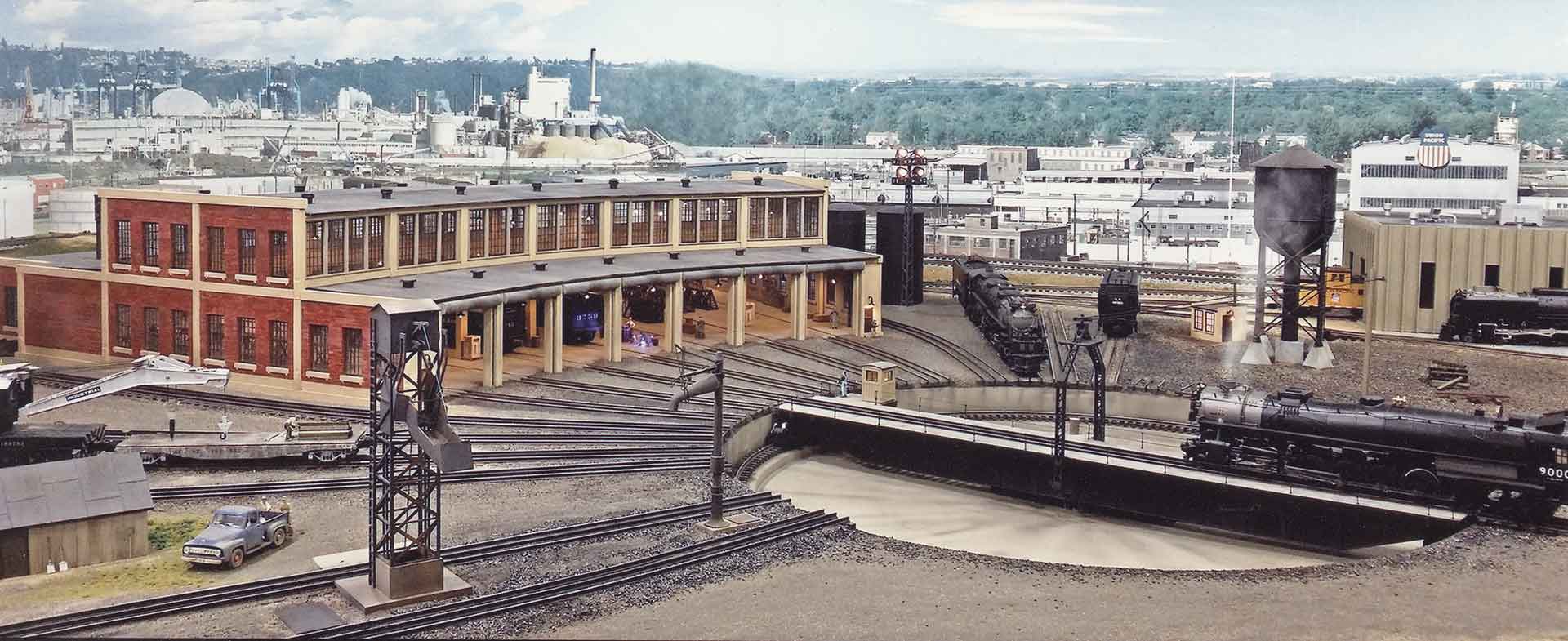
This is a Limited Edition Plaster Roundhouse Kit. I have produced 60 kits and there are less than 8 left. Because each kit may be ordered with different options, please allow up to 5 weeks for delivery. This allows time for ordering the laser cut windows and the custom packaging for your kit. If you have any questions, please call or email.
This roundhouse is inspired by the Norfolk & Western Ry. Roundhouse in Williamson, WV. The more-than-a-century-old prototype has a traveling overhead crane that traverses the open two story center section. It also uses roll up overhead corrugated steel roller doors. And, in case you’re wondering, I’ve discovered that roller doors came into existence sometime prior to 1925.
Although not an exact scale model of that or any particular structure, my model employs a common concrete beam and brick architectural style typically found in commercial and industrial buildings. The clerestory window treatment is derived from prototypical roundhouse design. The optional wooden doors are accurate copies of those on an existing roundhouse in Kansas City. Using artistic license, I’ve combined the finest features to create a distinctive and plausible design that will be an eye-catching focal point on any layout.
The windows are laser cut wood with adhesive on the back. The kit also includes Evergreen strip styrene, rear door, and other detail parts. The double freight door is by Tichy Train Group. The interior features basswood beams between stalls to support the roof. My instructions are a primer on plaster craftsman kit construction.
3 Stall Dimensions: Front – 18”, Side – 31-3/4”, Rear – 26 ¼”, Height to top of cornice – 6” (1st story) and 11” (2nd story).
The actual interior numbers for 3, 5, and 7 stall versions show:
Stalls
Width
Depth
3
25.31
31.48
5
40.39
32.65
7
55.12
34.25
Width represents the inner size between the back outside corners and does not include wall thickness. Adding the wall thickness would add an inch or slightly less to the figures for both width and Depth. The depth represents the length of a perpendicular line that bisects a line drawn between the front corners of the roundhouse. Since the structure is composed of angled sections that do not form rectangles, there is no place inside the structure as deep as the depth measurement.
You’ll note that dimensions are only shown for odd numbers of stalls. That’s because the design of the roundhouse features a center rear wall section that includes an employee and a double freight door entry. As such, it is wider than the other rear wall sections. So, in order to maintain the symmetry, additional stalls must be added in pairs – one on each side of the center stall.
The table below shows the IDEAL and the MINIMUM spacing in inches from the center of your turntable to the front center of the roundhouse:
Stalls
Total Degrees
IDEAL
MINIMUM
TT to RH
Height
Width
3
19.44°
39.79
23.27
6.27
31.48
25.31
5
29.56°
46.76
32.95
15.95
32.65
40.39
7
39.68°
49.69
38.24
21.24
34.25
55.12
9
49.81°
51.33
41.57
24.57
36.26
69.40
11
59.93°
52.38
43.86
26.86
38.66
83.09
13
70.05°
53.13
45.52
28.52
41.45
96.11
15
80.13°
50.69
43.79
26.79
44.59
108.35
17
90.30°
47.64
41.28
24.28
48.06
119.70
The numbers in the TT to RH column are arrived at by subtracting a 17” radius (using a 34” turntable) from those in the MINIMUM column. This is the minimum distance between the pit wall and the front center of the roundhouse. For smaller turntables, subtract the appropriate radius. The Height and Width show the space requirements for the roundhouse itself.
For example, the ideal spacing from the center of a turntable for a 5 stall roundhouse is 46.76” and the minimum is 32.95”. Subtracting the 17” radius (using a Millhouse River Studio 34” turntable) from those numbers gives you 29.76” and 15.95” respectively from the edge of the pit wall to the front center of the roundhouse. For even closer distances, each successive track on either side of the middle stall will have to be bent progressively closer to the middle after entering the stalls. The end stall tracks will require the most bend. Some modelers bend their end stall tracks between the turntable and the roundhouse. Although this is not prototypical, it is often an acceptable compromise within our space limitations.
One final note about track spacing: The track spacing at the pit wall is critical. You will have to slightly modify your ties to reach the ideal distance between the pit wall and the roundhouse. In the example above, at 29.76” you’ll have to cut about 3/16” off each tie leaving 3/8” between the outer rails of adjacent tracks 1, 2 and 4, 5 at the edge of the pit wall. Simply put, as the distance between the turntable and the roundhouse increases, the space between adjacent tracks at the pit wall decreases in order to maintain a straight line. And, as the number of stalls increases, the spacing between tracks decreases. In case you’re wondering, I have verified that there is sufficient space to accommodate any likely number of stalls. On the prototype, the rails from adjacent stall tracks often touch each other at the pit wall.
Note: I highly recommend the Millhouse River Studio Turntable shown in the photo — the finest turntable on the market featuring all metal construction.
Extension (Optional)
The beauty of my extension is that it includes enough material to extend 5 stalls of a 5 stall roundhouse thus preserving the symmetry of the back wall. Essentially, you’re moving the entire back wall of the roundhouse further back. However, since the back wall remains the same size, if we simply extended each side wall from its original position, the back wall would not be wide enough to span the increased distance between them. So I provide short jog walls at the original back corners of the roundhouse. This effectively makes up for added width. You have a choice of 3 lengths for the Extension: 2 ½, 4 13/16 and 7 ¼ inches. The longer the extension—the longer the jog.
NOTE: You can extend the entire back wall for any number of stalls but you would have to purchase some additional interior support beams and roof pieces for anything beyond 5.
First let’s look at words scale and gauge. Although they’re often used interchangeably, they refer to two different albeit related things. Scale is the proportion to life size expressed as a ratio: 1/48 or 1:48 for O Scale or ¼ inch = 1 foot.
Strictly speaking, gauge properly refers to the distance between the rails. So in O Scale, the track gauge would be 1-1/4 inches. That equates to 5 scale feet, although in real life the distance is actually 4 feet 8-1/2 inches between rails. This discrepancy is negligible and will be addressed in another post. Since each scale – O, S, HO, N, Z has its own proportionate gauge, it’s easy to understand why gauge is often substituted for and understood to mean scale.
However, O Gauge is an all inclusive term as used by many 3 railers, especially those who run what Lionel refers to as “Traditional” sized trains. These trains are slightly smaller than scale sized models. Lionel uses the term “Standard O” to refer to its trains that are scale sized.
The letter O is what is used today as in O Gauge or O Scale. The confusion with the number 0 (zero) dates back to the early 1900s when the wide European track gauges were numbered 1, 2 and 3. 0 (Zero) gauge was smaller than 1 and is now what we call O Gauge.
I can hear some saying, “what difference does any of this make? Try doing an internet search substituting the number 0 (zero) for the letter O and see what happens.
Pretty much since day one of planning my O-Scale layout, I’ve known that I would eventually want to add quite a few chain link fences to the scenery. Chain link fences are EVERYWHERE in modern times, so it only makes sense that a train layout would have quite a few of them to keep would-be trespassers out of a train yard, a power plant, a factory or any other are where privacy is desired. To that end, several years ago I bought a chain link fence kit from Brennan’s Model Railroading. Dennis Brennan has become a good friend over the years and his expertise in scenery building has proved invaluable to me. A great majority of my speciality scenic supplies (fences, ground cover, track ballast etc.) come from Dennis. His chain link fence kit, when assembled properly, results in the most realistic O-Scale chain link fence on the market…period. When I bought the fence kit several years ago, however, the layout was not in a suitable stage to begin the installation of any fences so I put the kit into storage and waited…and waited…and waited.
Here we are several years later and, finally, the layout is getting to the point where I can begin to work on the finer details of scenery…such as fences! A few days ago I blew the dust off Dennis’ chain link fence kit and set to work.
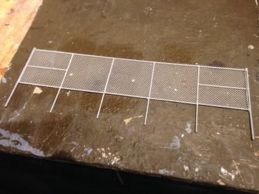
Upon opening the box I was initially a bit intimidated, to be honest. The box contained loads of pieces, some of which seemed to make sense and others that didn’t, as well a rather thick set of instructions. “Oh boy”, I thought, “what have I gotten myself into? This is going to be a nightmare of a project.” I’ve bought many kits over the years that had lots of parts and yet were sparse on the instructions and therefore were a royal pain to put together…much of the work consisting of guess work due to a lack of good directions. I began to think that the chain link fence kit might end up the same way, but then I remembered something about the guy who sells these kits. Dennis Brennan is no slouch when it comes to making kits. He is an accomplished writer and has a real talent for clear and concise instruction. With that in mind, I kicked back in my chair and read his instructions from beginning to end. His directions actually made sense! They were completely logical and very easy to follow. Suddenly I realized, “Hey, I think I can do this. This isn’t going to be hard after all. Tedious, maybe, but not hard.” And so a few days days ago I began work on my first chain link fence. The kit has all the parts to make about 8 feet (384 scale feet) of fencing that features a metal frame and realistic chain linking within the frame. The list of tools needed is a bit lengthly, but it’s nothing the average train guy doesn’t already have in his shop. The assembly of the fence frame does require the use of a soldering iron, but Dennis was thorough enough in his directions to actually include a bit of “Soldering 101” for newbies.
So my first chain link fence, which will surround a Lionel water tower, is well underway and looking great so far. I’m not to the point where I’m doing a good job of making the standard sections of fence. The next challenge will be to make a gate. I’m not worried, however, because the instructions that come with the kit do a great job of explaining how to make gates. I’ll post some more pictures here when my first gate project is complete. Wish me luck!